Your shopping bag is empty

MIG Welding Parameter Settings and Guidelines
- Comments: 0
- Categories: Frequently Asked Questions
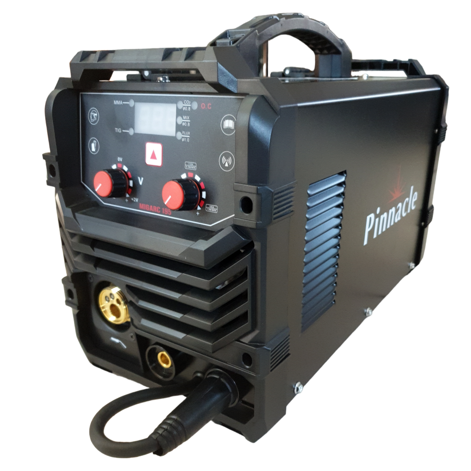
So you have purchased your Pinnacle MIGARC or PrimiMIG Welding Inverter and you are new to MIG Welding? Here is a brief guideline to getting a starting point with your MIG welding machine parameters.
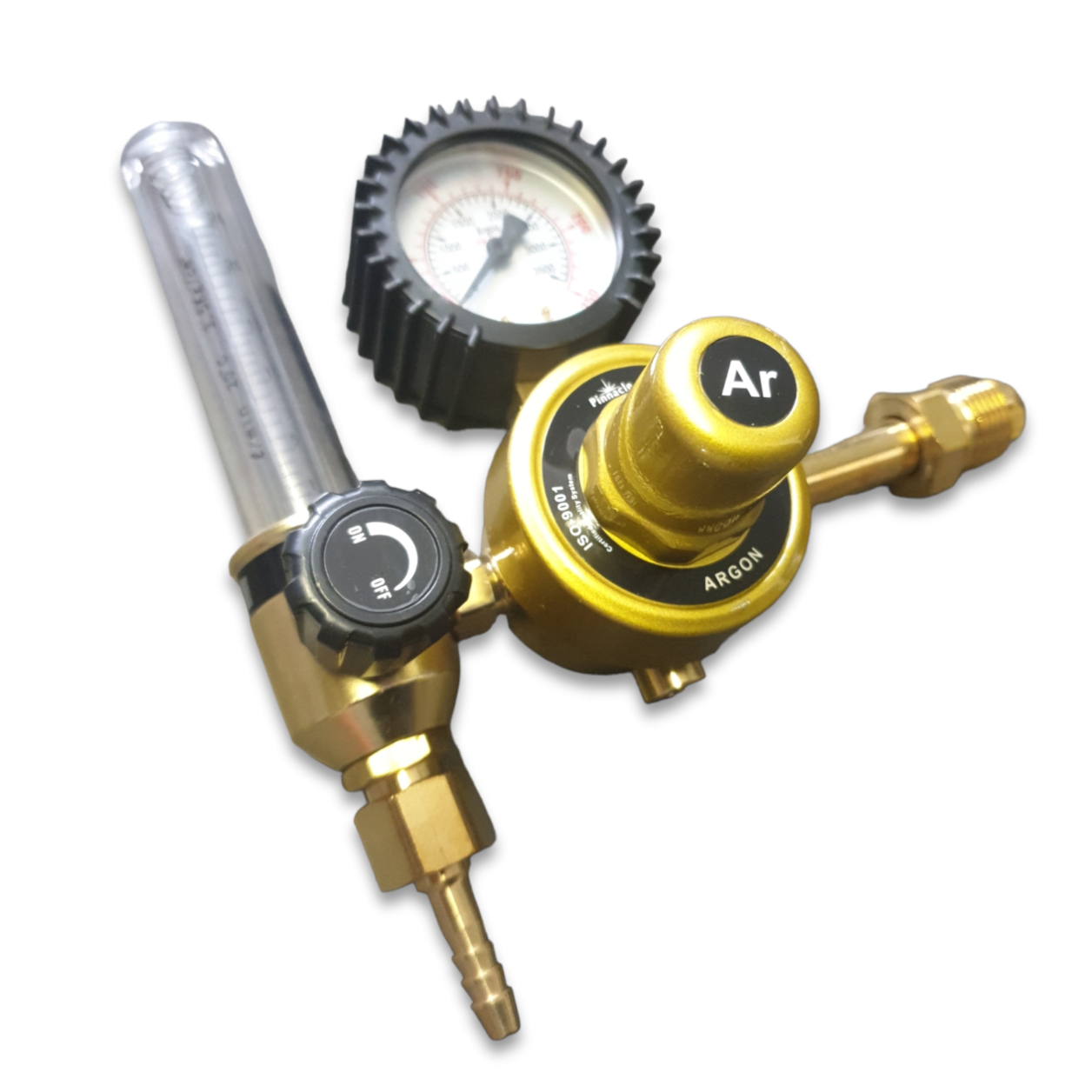
First let's talk about Gas:
CO2 gas is economical and has deeper penetration on steel, but may be too hot for thinner metals.
75% Argon / 25% CO2 is better on thin steels, has less spatter and better bead appearance.
• Both Gases are for Indoor use with no wind.
• For auto body, manufacturing, fabrication opt for 75/25 Argon/Co2
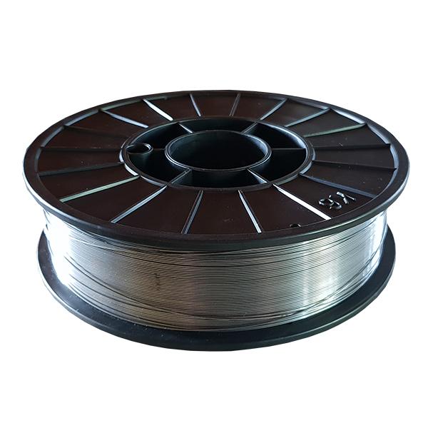
• Gasless Flux Core is reccomended for structural welding and is not siutable for thinner materials, 1.6mm and up. See more info below.
Let's get a basic understanding of what each control manipulates:
Amperage/Current Control: The Amperage control is responsible for two things, Wire Speed & Heat (Current). This will control the heat of your weld and manipulate the penetration and filler transfer.
Voltage Control: The Voltage Control is responsible for the frequency of the weld. The Voltage will control the width of the weld, a higher voltage produces a wider weld pool.
Gas Flow: Gas flow is usuaslly between 15-20 CFM, this is dependant on the welding material and thickness, more detail will be displayed below.
On some models you may have an inductance control, this is used more for Flux Core welding and TIG Welding on Multi-Process machines. For starters this setting is not important but there will be a follow up detailing more on this.
IMPORTANT NOTE: Before we continue we also need to understand that there are many factors that will affect your welding parameters and these parameters are mere guidelines put together to help you understand the process of MIG Welding and teach you how to determine your parameters. Things that influence parameters can be welders hand speed, contamination of material, gas quality and more, but with the info below you will understand how to get the parameters under control in no time.
First Step to Setting MIG Welding Paramters:
The first setting we need to look at is the material thickness we are going to be welding, before we start MIG Welding the amperage needs to be adjusted according to the material thickness.
Having a look at the chart below we can follow the material thickness column and set the amps more or less according to the chart. There is also a formulae that can be used to calculate different material thicknesses at the bottom of the chart.
| MILD STEEL GAS WELDING PARAMETERS | ||||
| SHORT CIRCUIT TRANSFER | ||||
| Material Thickness Parameter | Voltage Setting | |||
| Wire Speed & Current | Frequency of ARC | |||
| Formulae: mm thickness divided by 25.4 multiplied by 1000 equals Amps Setting | ||||
| These Parameters will differ according to hand speed, steel contamination, gas quality and other factors. | ||||
| Material Thickness (mm) | Wire Diameter (mm) | Voltage (V) | Current (A) |
|---|---|---|---|
| 0.5 | 0.6 | 15 - 17 | 20 - 30 |
| 1.0 | 0.6 - 0.8 | 16 - 18 | 30 - 40 |
| 1.5 | 0.6 - 0.8 | 17 - 19 | 35 - 50 |
| 2.0 | 0.8 - 1.0 | 18 - 20 | 40 - 90 |
| 2.5 | 0.8 - 1.0 | 19 - 21 | 50 - 100 |
| 3.0 | 0.8 - 1.2 | 20 - 22 | 90 - 120 |
| 3.5 | 0.8 - 1.2 | 21 - 23 | 100 - 130 |
| 4.0 | 0.8 - 1.2 | 22 - 24 | 120 - 150 |
| 4.5 | 0.8 - 1.2 | 23 - 25 | 140 - 170 |
| 5.0 | 0.8 - 1.2 | 24 - 26 | 150 - 180 |
| 5.5 | 0.8 - 1.2 | 25 - 27 | 160 - 190 |
| 6.0 | 0.8 - 1.2 | 26 - 28 | 180 - 210 |
NOTE: Some MIG Welding Machines have a serperate wire feed control, this is not always nessecary and can make learning MIG Welding very difficult as your Wire Speed to Current should always remain in ratio with each other. Hence the reason MIG Welders have Current and Wire Speed on one control, and serperate controls are not nessecary for general welding but may be required for more specific controls on more intricate welding projects.
Now that we have the correct Amperage setting it's then time to have a look at the Voltage. Voltage determines height and width of the bead by controlling the frequency of the Short Circuit ARC Process as per the chart the guideline provided may be perfect for your weld or it may not be 100%.
Best way to Set the voltage: If no chart, manual or specifications are available for setting the correct voltage, you can try this: While one person welds on scrap metal, an assistant turns down the voltage until the arc starts stubbing into the workpiece. Then, start welding again and have an assistant increase the voltage until the arc becomes unstable and sloppy. A voltage midway between these two points provides a good starting point.
There is a relationship between arc voltage and arc length. A short arc decreases voltage and yields a narrow, ropey bead. A longer arc (more voltage) produces a flatter, wider bead. Too much arc length produces a very flat bead and the possibility of undercut.
By understanding the process and responsibility of the controls, Amps & Volts, you can now spend some time with some scrap metal perfecting your parameters by adjusting the controls until you acheive the perfect weld.
NOTE: When you first start MIG Welding and you find a perfect spot, make a note on the material thickness and the parameters, Volts and Amps, that work for you. After a few months you will be setting your machine with your eyes closed.
Below are examples of what a weld looks like with incorrect parameter settings.
Wire Speed & Current too Low:
Insufficient Amperage displays a narrow convex bead with no tie-in at the toes of the weld marking.
Wire Speed & Current too High:
Over compensating the Current & Wire Speed leads to poor ARC starts, excessive spatter, poor penetration (Bead is noticably on top of the weld material) and wide weld beads.
Voltage set too Low:

Low Voltage again provides poor or no tie-in at the toes of the weld and a convex bead profile that results in poor penetration & ARC starts with very little weld pool control.
Voltage set too High:

Too much voltage is marked by poor arc control, inconsistent penetration and a turbulent weld pool that fails to consistently penetrate the base material.
Hand Speed / Travel Speed too Fast:
A narrow, convex bead with inadequate tie-in at the toes of the weld, insufficient penetration and an inconsistent weld bead are caused by traveling too fast.
Hand Speed / Travel Speed too Slow:
Traveling too slow introduces too much heat into the weld, resulting in an excessively wide weld bead and poor penetration. On thinner material it may also cause burn-through.
Too Little or No Shielding Gas:

A lack of or inadequate shielding gas is easily identified by the porosity and pinholes in the face and interior of the weld.
What a good weld should look like:

Notice the good penetration into the base material, flat bead profile, appropriate bead width, and good tie-in at the toes of the weld (the edges where the weld metal meets the base metal).
Gasless Flux Core Welding Parameter Settings
Below is a Chart for welding with Flux Core (Gasless) MIG Welding Wire. Flux Core Gasless Wire is designed for structural welding, this wire provides a deeper penetration for thicker steel and is reccomended for 1.6mm thickness and up.
Flux Core tends to produces at a much higher heat on ARC and will require less Amperage with slower hand speeds or travel speeds.
| MILD STEEL GASLESS FLUX CORE WELDING PARAMETERS | ||||
| SHORT CIRCUIT TRANSFER | ||||
| Material Thickness Parameter | Voltage Setting | |||
| Wire Speed & Current | Frequency of ARC | |||
| inch | mm | Amp Range | No Gas | |
| 0.039 | 1.000 | 70 A | 13 V | |
| 0.059 | 1.500 | 85 A | 16.5 V | |
| 0.079 | 2.000 | 110 A | 18.5 V | |
| 0.098 | 2.500 | 120 A | 19 V | |
| 0.118 | 3.000 | 150 A | 20.5 V | |
| 0.157 | 4.000 | 160 A | 21.5 V | |
YOU MIGHT ALSO LIKE

MIG Welder: Everything You Need To Know
- Nov 01,2023
- 0
MIG Welder: Everything You Need To Know - A Comprehensive Guide to Machines, Techniques, and ...
How does gasless MIG welding work?
- Jun 21,2023
- 0
Gas vs. Gasless MIG Welding: What’s the Difference? How does gasless MIG welding work? Intro...

Pinnacle MIGARC 195 MIG Welding Machine User Guide
- Apr 24,2023
- 0
Introduction: The Pinnacle MIGARC 195 is a versatile MIG welding machine designed for a wide ...